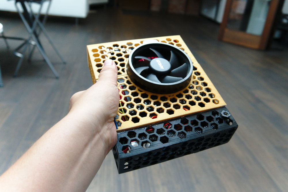
I built a very minimal PC using my 3D printer. I’m still a bit worried about damaging the fan/heatsink when I transport it, but I’m quite happy about the cooling, performance, and portability so far.
You can find the OpenSCAD and STL files for modifying and printing the case here
My brother and I were talking about the possibilities of 3D printed computer cases. I saw a neat little mini-itx build1 on PCPartpicker and was inspired to buy the components I needed to build this system2.
| CPU | AMD Ryzen 5 2400G 3.6GHz Quad-Core Processor |
| Motherboard | ASRock - AB350 Gaming-ITX/ac Mini ITX AM4 Motherboard |
| RAM | Corsair - Vengeance LPX 16GB (2 x 8GB) DDR4-3000 Memory |
| Storage | Western Digital - Black PCIe 256GB M.2-2280 Solid State Drive |
| PSU | ATX 300W 12VDC Power Supply + Laptop Style 90W 12VDC Power Brick |
| Case | Custom 3D-printed Mini-ITX case |

I have a few reasons for building this system. I was running a dual-seat configuration before, but having two stations glued into one computer caused quite a few annoying problems. When I travel, I usually bring my laptop, but I find that my laptop doesn’t have good enough game performance. Hell, my current laptop (A Dell Latitude E5450) can barely run everything I need it to run at work. I wish I could have thrown 32GB of RAM in this machine. Unfortunately, even 16GB cost more than my processor, so I settled for 16GB. The machine is very strong and adaptable. I’ve run both Linux and Windows 10 Pro on it and I’m very happy with its performance. I knew it wasn’t going to be the most performant system, but I’m really hoping that the AM4 socket gets an APU that makes this machine a no-brainer upgrade.
When I was browsing Newegg, Amazon, and other sites to see what Mini-ITX cases and power supplies were available. I found that most cases are designed to accomodate a discrete GPU, Optical Drive, and 2.5" or 3.5" SATA Drives. While I may want to add a 2.5" SSD into my build in the future, I don’t currently have a need for any of these extra components. They say that to a kid with a hammer, every problem looks like a nail. Well, to a nerd with a 3D Printer, I try to print a solution to every one of my problems.
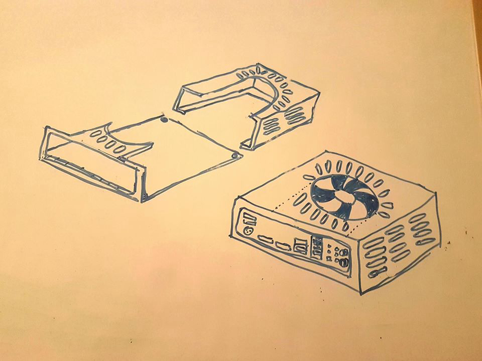
I figured I could make some kind of two piece clamshell case. I saw a really cool build3 on Thingiverse and I felt inspired. I like the aesthetics of an exposed central fan. I’ve heard that most mini-pc’s get really hot, so cooling was a major concern.
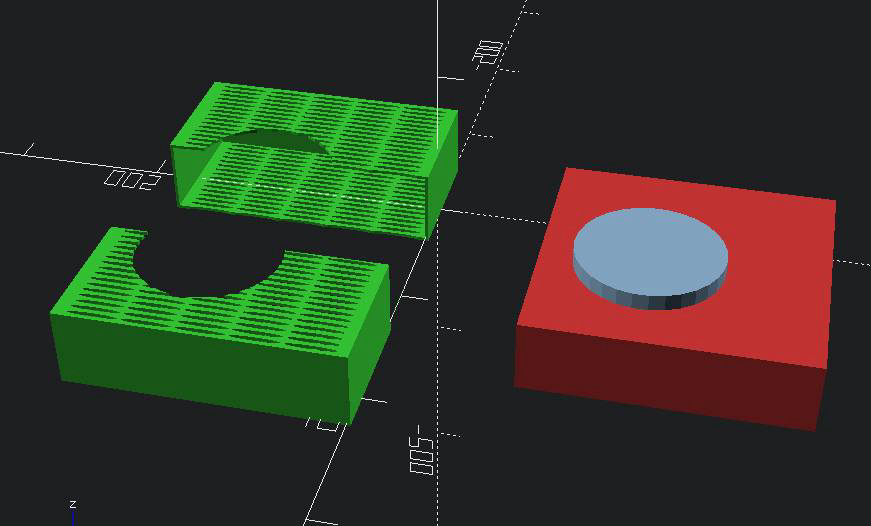
I like a lot of things about OpenSCAD. Since I spend a lot of time writing code, it felt natural to also use code to draft and design physical objects. I’ve tried a few different CAD programs, but this is the one I’ve become most familiar with in the last couple years.

At this point, I hadn’t recieved the parts, so I actually didn’t know the exact measurements, let alone shape of all of my components. I started by approximating the shape, size, and position of all of the components. I tried to write the OpenSCAD code in a generic way so that I could "dial-in" the design for any motherboard and fan combo.
I printed the case using my HICTOP 3DP-12. It’s a Prusa i3 clone that I purchased on sale a couple years ago. As long as you can print 180mm x 180mm, you should be able to print this. I chose to use PLA, which is the only material I really use. The case is currently held together by twist ties and hot glue.
I’ve had to make about 3 copies of every printed part in this design. I had to eyeball a few measurements and approximate some shapes.
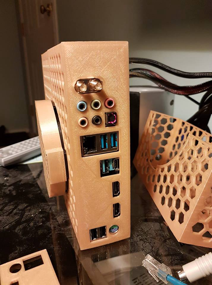
The honeycomb design was sort of an accident. I was experimenting with shapes and placement and actually considered rectangular slats at first. I had seen some honeycomb cases and structures on Thingiverse in the past, so I figured I’d give it a shot. It was easy to make the hexagonal columns by creating a 6 sided approximation to a cylinder.

The honeycomb pattern helped me minimize material usage while also allowing for great airflow. I had to print a handful of cases to get the fan placement and motherboard clearance just right.
At this point, I was running a full size desktop power supply. Each side of the case was wide open. I needed to get the fit of all the panel components just right.
I lucked out and realized I could use the square panel slot to test fit the panel components without reprinting the entire half-shell.
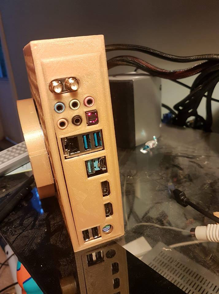
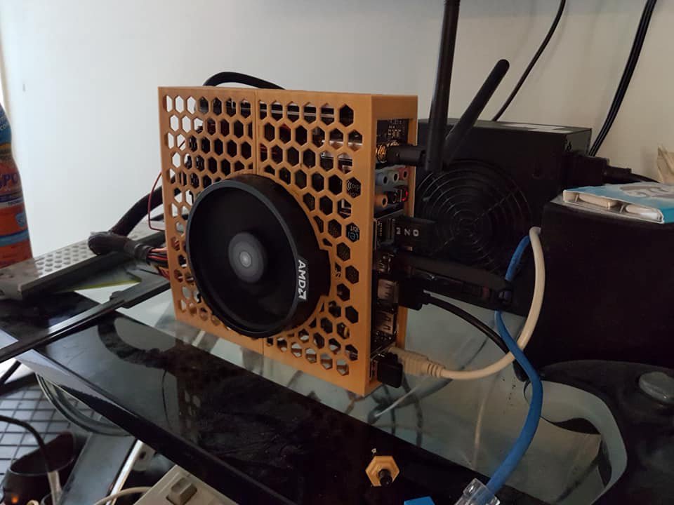
It took a few test prints, but I finally found the right spacing for all the different connectors on the rear panel. I could definitely dial-in the settings even further, but I’m pretty happy for the moment.
I’d actually like to improve the cooling on the panel. It’s solid right now, and since I really want maximum airflow, I don’t want to cut off one whole side of the case.
So at first I was just "hot-wiring" the power and reset buttons. I used a female to female connector to bridge either the power or reset circuit to ground. When I finally commited to building the full self-contained case, I needed to solder wires to the power switch and allow it to be mounted to the case. I cut a female-female connector in half, stripped the wire, and soldered it to the power switch which was inserted into the 3D-printed button-mount.
Unfortunately, although I bought two switches, I didn’t realize that one of the switches I bought was actually NC rather than NO4. I had to superglue the switch onto the case. I was able to insert it as a press-fit component, but it needed glue to stay in place when the button was depressed.
The two halves are currently held together by 4 twist-ties. The ATX power adapter cage is held on by clips and hot glue.

The machine is currently running Windows 10. The box can run and stream games at > 30fps at medium-high settings. I was running Arch Linux on it at first. I had to update to the latest BIOS and kernel to get it running, but it was very impressive. Since my main machine is a Linux workstation, I decided to risk purchasing a copy of Windows 10 Pro from Kinguin.net It was pretty cheap, but since it was an OEM license and I am not entirely familiar with the Windows install experience, it took me a few days to get the license properly validated. I haven’t yet done formal benchmarks, but the first few weeks, I ran the DDR4 at the default 2133 Mhz. I brought the RAM up to 3200Mhz without looking at the rated speed and it just worked. I’m getting some crashes which might be due to the undersized PSU brick I’m currently using since it’s only designed to supply 90W of power.
The build that inspired me: https://ca.pcpartpicker.com/b/nxTBD3↩
My part list: https://ca.pcpartpicker.com/list/9Cxvq4↩
The inspiration for the case: https://thingiverse.com/thing:1899854↩
Normally Open and Normally Closed Switches: https://learn.sparkfun.com/tutorials/switch-basics↩